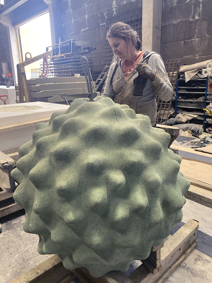
Above: A pollen grain from ragweed supersized in eco-friendly natural concrete. The concrete sculpture is one metre in diameter, weighing approximately one and a quarter tonne – about the same weight as a small car! For comparison, its ‘little brother’, i.e. the source pollen grain it was based upon, was approximately twenty microns in diameter, thus enlarged by a factor of 500,000x. Photo courtesy of Saara Ekström.
You’d be forgiven for thinking that a microscope would be essential to explore the intricate 3D structure of a pollen grain. Well, how about climbing on top of it and exploring it by hand instead? Confused? Please read on.
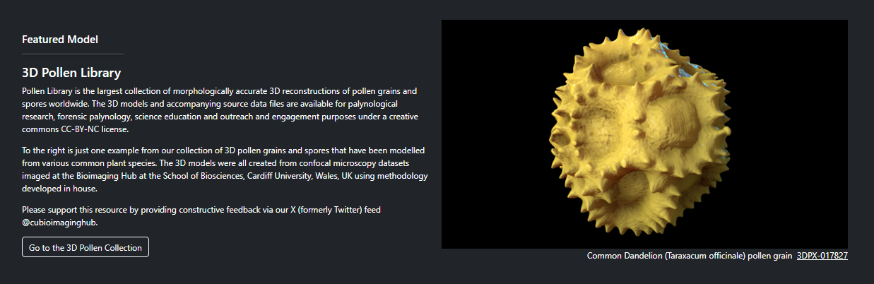
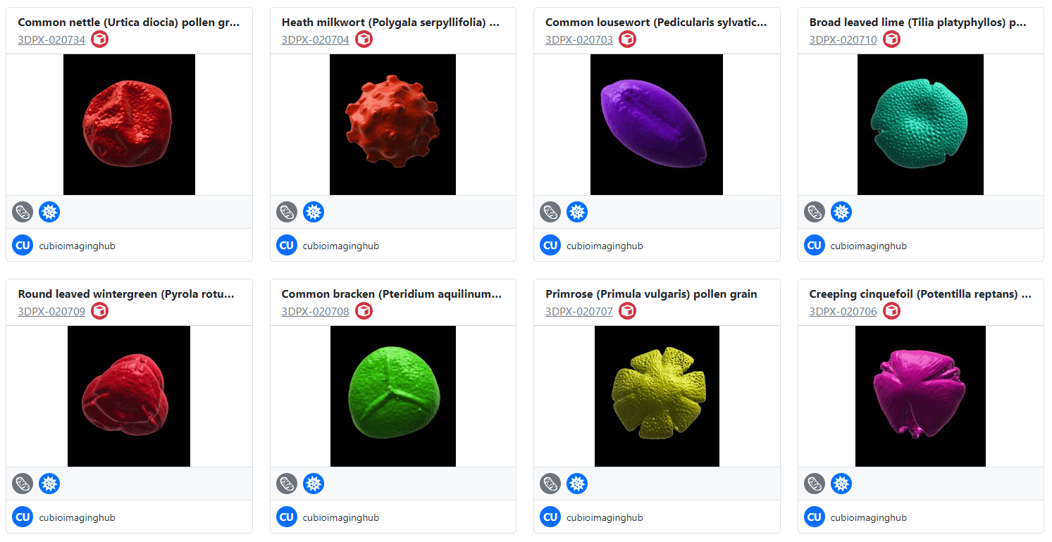
If you’ve visited this site before then, chances are, you’ll be aware that I enjoy ‘noodling around with pollen’ : ) Over the last seven years, the Bioimaging hub has developed and refined methodology that permits 3D printing and both virtual and augmented reality (VR and AR, respectively) visualization of microscopic samples such as pollen grains for use in educational and immersive learning experiences. A direct offshoot of this work has been the development of what is currently the largest online repository of 3D pollen grain models worldwide. To date, I have curated over 170 published, DOI-referenced 3D pollen models from over 150 species of plant which can be downloaded free, for non-commercial usage, via the Bioimaging Hub’s 3D Pollen Library Collection on the NIH3D website. You can read more about the evolution of this resource in the links below (including a recent article I have written for the Royal Microscopical Society In Focus magazine, December edition – to follow).
Recently, the project took another interesting and unexpected evolutionary turn. I was contacted by Finnish visual artist and film maker, Saara Ekström, who pitched to me an amazing idea for a collaboration: gigantifying some of our 3D pollen models as public art sculptures for an elementary school in Helsinki, Finland. The plan was to cast the sculptures in coloured eco-friendly natural concrete at a range of sizes between 0.7 and 2 metres to create a magical ‘Alice in Wonderland’ outdoor learning environment for the children, helping to raise their awareness of the unseen, natural world and fostering an understanding of ‘one of nature’s smallest and most essential components’. An absolutely wonderful idea!
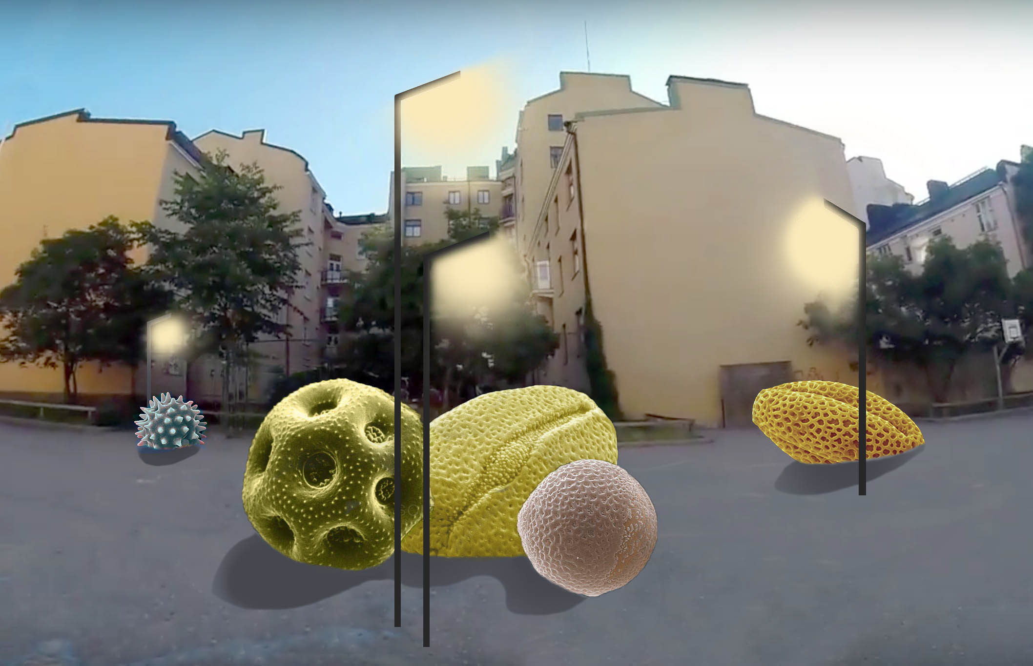
Above: Concept art for the 3D pollen sculptures courtesy of Saara Ekström.
As part of the project, a protected piece of old-growth forest, purchased from the Finnish Natural Heritage Foundation, will be presented as a gift to the School, thus preserving something that is vitally important to future generations of children and linking the pollen sculptures to this natural ecosystem. Having kids of my own (and ever mindful of the ongoing environmental crisis) I was delighted to support Saara’s ambitious project. The thought that pollen grains from flowers in my back garden would be reproduced as two metre concrete megaliths nearly two thousand miles away in Helsinki was also simply irresistible! Stonehenge, nothing ; )
Saara identified four pollen species of interest from our collection: blue passion flower (Passiflora caerulea); common thyme (Thymus vulgaris); black elderberry (Sambucus nigra) and common ragweed (Ambrosia sp.) which exhibited strikingly different morphologies and surface ornamentation (see below). Some of the more spiky and ornate pollen grain species (e.g. common daisy, Bellis perennis) in our collection were deliberately avoided since the children would have to be able to climb on them safely without risk of impalement!
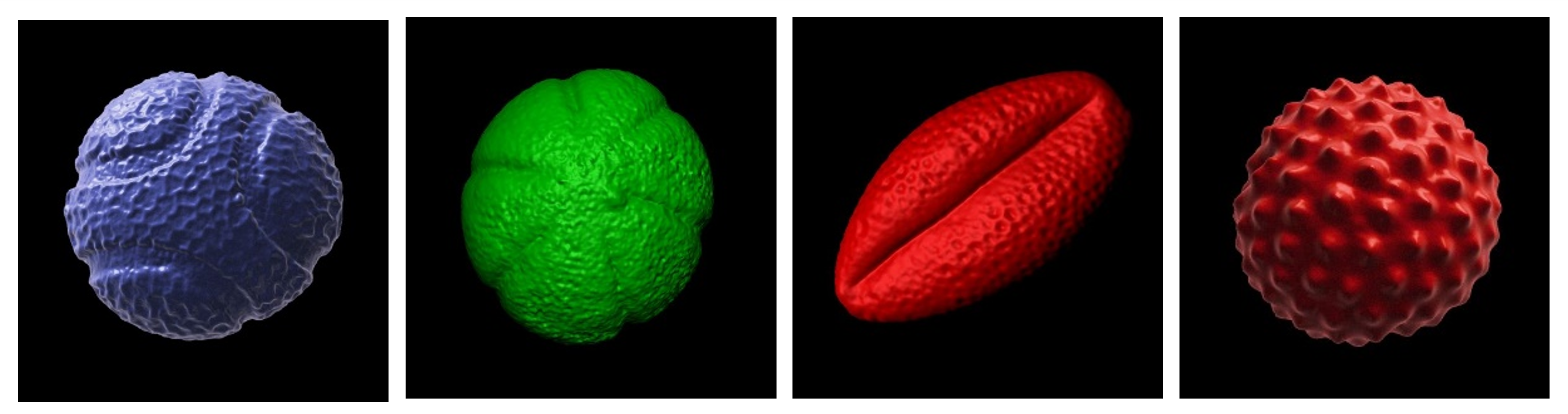
Above: the four species of pollen grain to be supersized as concrete sculptures. From left to right: blue passion flower; common thyme; black elderberry and common ragweed. 3D pollen models created by Tony Hayes. The 3D models are available for download for non-commercial usage from the Bioimaging Hub’s 3D Pollen Library collection at NIH3D.
So how does one create a gigantic concrete sculpture of a microscopic pollen grain? Well, this was one of the first things I asked Saara, who was more than happy to explain the steps involved. First, our 3D pollen meshes are downloaded from the NIH3D website and scaled up into virtual models of the sculptures using CAD software, taking care to retain as much surface detail as possible (see below). The pollen grain mesh is also truncated in order to form a flat, stable base (we wouldn’t want them to accidentally roll onto someone’s foot, after all!)
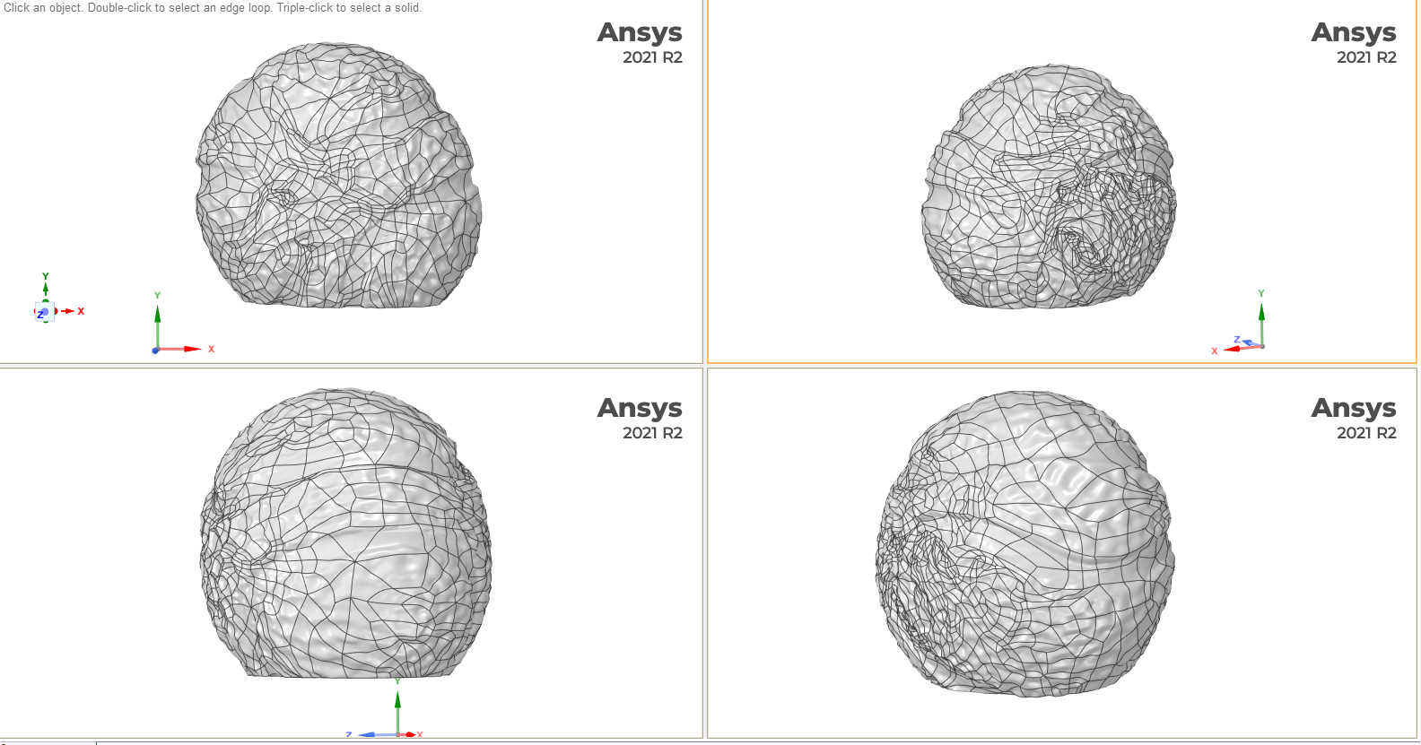
Above: 3D meshes of the pollen grain (Blue passion flower shown here in multiple orientations) are used to program a tool that mechanically carves a negative form into styrofoam thereby forming the casting moulds. Screen grabs courtesy of Saara Ekström.
The meshes are then used to program a tool that mechanically carves a negative form of the 3D models into large, high density styrofoam blocks to create the complementary halves of the casting moulds, as shown below.
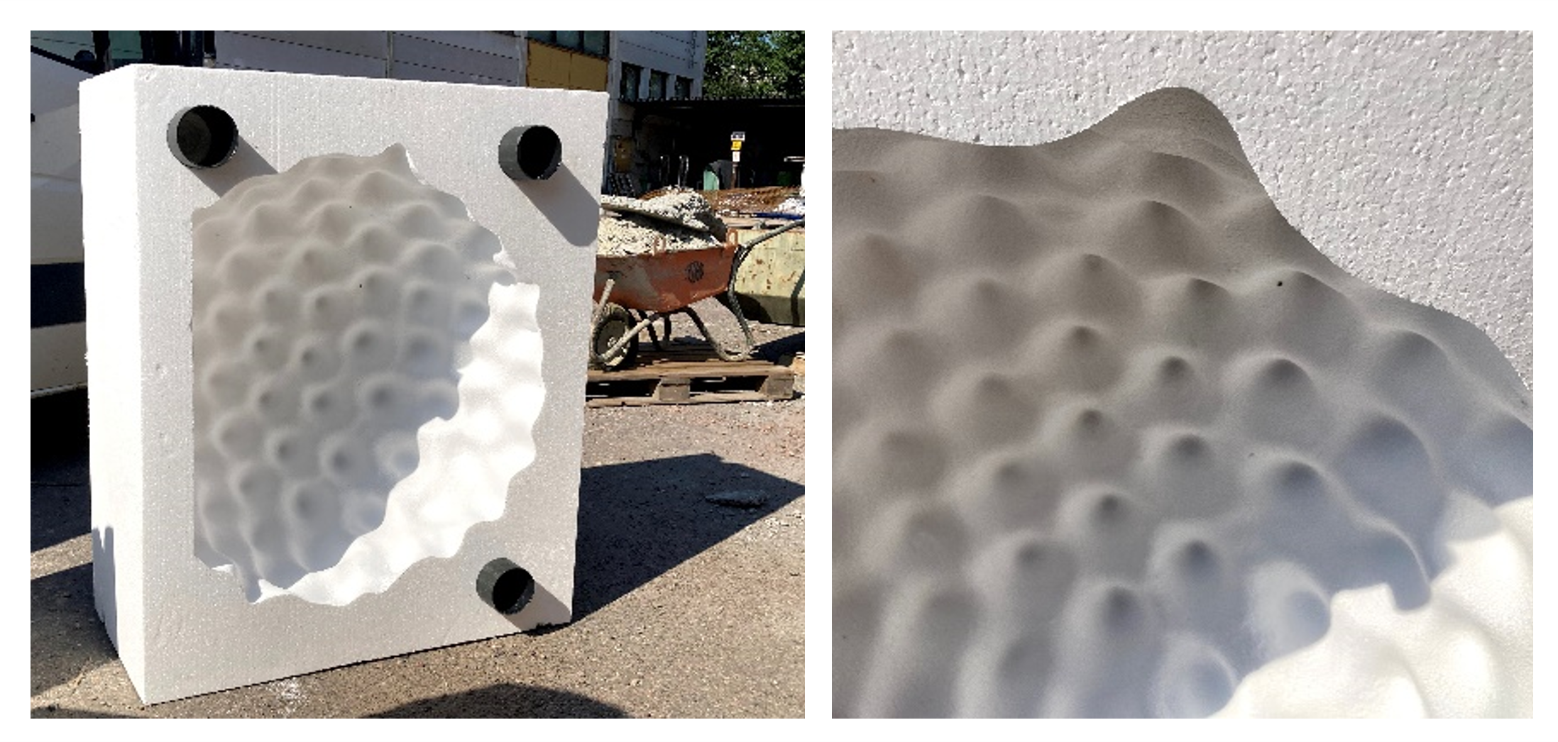
Above: The casting moulds (Ragweed pollen shown here) are mechanically carved out of high density styrofoam blocks and are able to record surface detail with high fidelity. A flat base has been introduced into the mould (left panel) to maintain stability of the resultant sculpture. The protruding black cylinders allow the two complementary halves of the mould to be held tightly together during the casting process. A wheel barrow in the background demonstrates the large scale of the moulds. Photos courtesy of Saara Ekström.
Once the moulds are created, steel reinforcement is incorporated into the cavity to add structural strength to the sculpture. Coloured eco-friendly natural concrete is then cast, using different coloured pigments for each pollen species. Once the concrete has cured, the moulds are removed and (in the words of Saara) ‘Volia, a microscopic pollen grain has grown to nearly monumental proportions!’
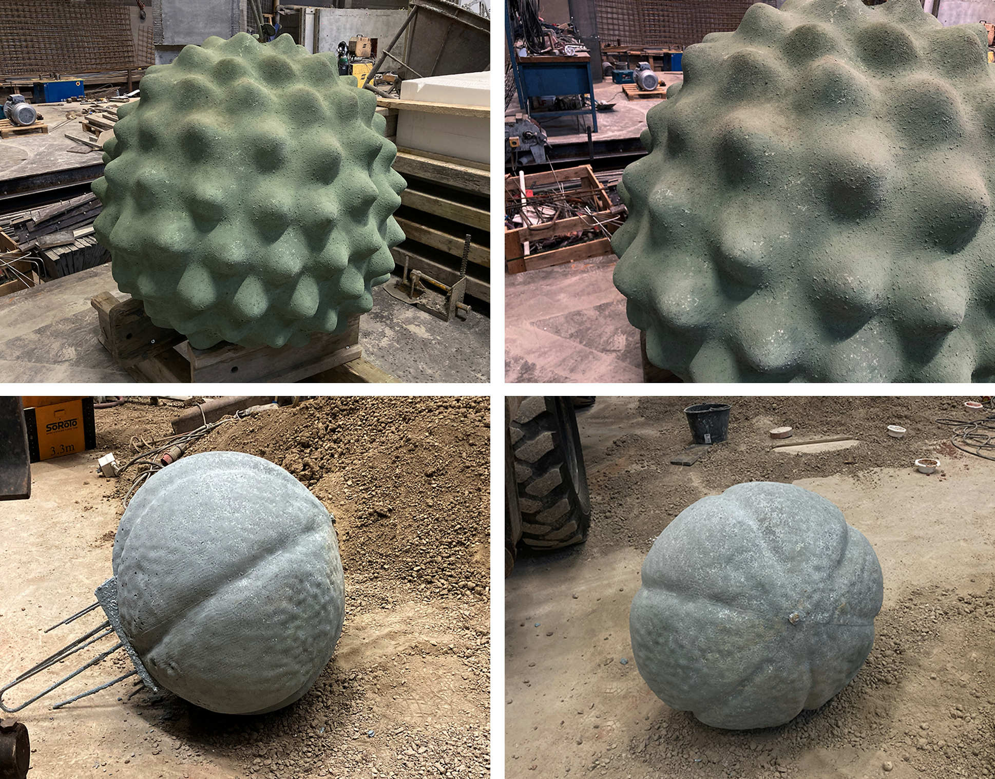
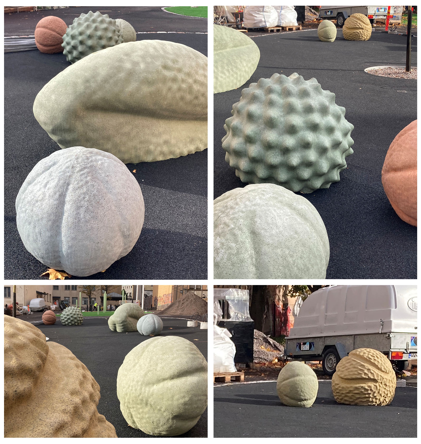
Above: The unfinished concrete pollen sculptures following removal of the styrofoam moulds. Top panel shows Ragweed pollen, bottom panel shows Thyme pollen. Rebar steel reinforcement can be seen protruding from the base of the thyme pollen sculpture (bottom left). Photos courtesy of Saara Ekström.
The concrete sculptures are then hand finished and a coloured protective coating is added before they are moved to their final destination, the Kallio primary school in Helsinki. At the site they are carefully lowered into place by crane. Rubber protective matting is then installed around each sculpture.
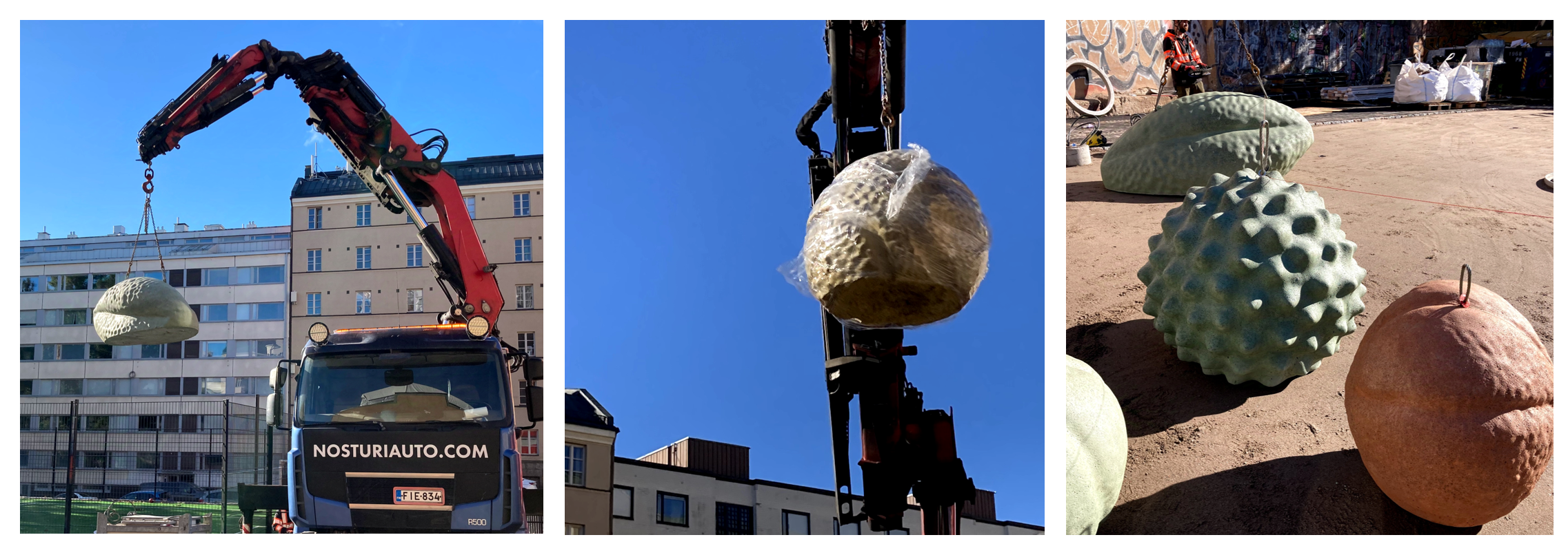
Above: A crane lowers the concrete sculptures into place at the Kallio primary school, Helsinki. Left panel, black elderberry pollen sculpture; centre panel, passionflower pollen sculpture; right panel, some of the concrete sculptures in situ. The precise placement of the sculptures is specified in the artists design. Photos courtesy of Saara Ekström.
Above: The finished pollen sculptures surrounded by rubber safety matting. There are seven sculptures in total in a range of different colours: four of the thyme pollen and one each of the other three species,. The area will be landscaped with trees and mood lighting to create an inviting ambience. Photos courtesy of Saara Ekström.
As the winters are long and dark in Finland, customised mood lighting will illuminate the sculptures creating a warm and inviting ambience, as depicted in the concept art above. I think it is fair to say that Saara, has done an absolutely monumental job!
The pollen sculptures were commissioned by the City of Helsinki and will be administered by the Helsinki Art Museum who are responsible for all the city’s public art collection.
AJH 25/09/2024
Addendum
Following installation of Saara’s pollen sculptures, I thought it might be a good idea to provide Kallio primary school with 3D printed models of the same species of pollen so that they could be used as learning resources for their science classes. Although nowhere near as impressive as Saara’s mighty megaliths, the 3D prints can be held and examined by hand for kinaesthetic (i.e. tactile) learning experiences by the children.
The 3D printed model were supplied with laminated information sheets including the common name of each pollen species in English, Welsh and, of course, Finnish, and a QR code to their respective digital 3D mesh on NIH3D.
We hope they go down well.
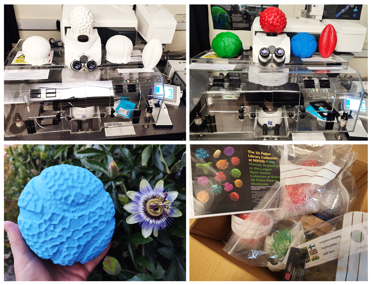
Above: 3D printed models of the four different pollen species created for the Kallio primary school, Helsinki. Top panel: the 3D prints before and after finishing (left and right panels, respectively) presented on top of the Zeiss LSM880 confocal microscope used in their creation. Models shown from left to right (with Welsh and Finnish translations in parenthesis): thyme pollen (paill teim, timjamin siitepöly); ragweed pollen (paill bratlys, tuoksukin siitepöly); passion flower pollen (paill blodyn y dioddefaint, kärsimyskukan siitepöly) and black elderberry pollen (paill eirinen ysgaw ddu, mustaseljan siitepöly) Bottom left panel: 3D print of a pollen grain sampled from the passion flower plant growing in my back garden. Bottom right panel: the 3D pollen prints packed up for their journey to the Kallio primary school, Helsinki.
AJH 25/11/2024
Further reading
- Hayes, A.J. (2024). The 3D Pollen Library Collection at NIH3D: From humble beginnings to the largest open-source collection of online 3D pollen models worldwide. infocus Magazine 76 (Dec), pp. 4-17. DOI: 22443/rms.inf.1.277
- Perry, I., Szeto, J-Y., Isaacs, M.D., Gealy, E.C., Rose, R., Scofield, S., Watson, P.D., Hayes, A.J. (2017) Production of 3D printed scale models from microscope volume datasets for use in STEM education. EMS Engineering Science Journal. 1 (1): 002
- IN FOCUS: Bigging it up: 3D printing to change the shape of microscopy (February, 2016).
- IN FOCUS: Development of a 3D printed pollen reference collection (August, 2016)
- IN FOCUS: 3D Pollen prints not to be sniffed at: printing pollen for the met office (July, 2017).
- IN FOCUS: Immersive Microscopy: 3D visualisation and manipulation of microscopic samples through virtual reality (February, 2019)
- IN FOCUS: Plastic fantastic: making pollen models for the National Botanic Garden of Wales.(October, 2019)
- IN FOCUS: AR Palynology: probing the reality of nature/nature of reality (November, 2022)
- THE 3D POLLEN LIBRARY: from humble beginnings to the largest online collection of morphologically-accurate 3D printable pollen models.
- IN FOCUS: The ‘3D Pollen Library’: An Update.


