Fault Current Limiter surge protection concept based on a permanent magnet biased core by Jeremy Hall and Faris Al-Naemi
25 May 2021
Introduction
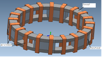
A new magnetic structure is described, based on interacting AC and DC fluxes in a device comprising permanent magnets and soft magnetic alloy cores in a novel, highly efficient arrangement to render the composite core electrically invisible under normal conditions, but able to respond quickly with a high impedance to limit damaging fault currents.
Aims & Objectives
A small, bench-top prototype was built to demonstrate the concept for a distributed magnet, orthogonally biased FCL. The test was designed to compare the current limiting capability of the FCL with an air-cored reactor coil of similar dimensions. The prototype was designed to operate with a normal current of around 3 Amps and a prospective fault current of around 30 Amps.
Materials & Methods
FEM Modelling
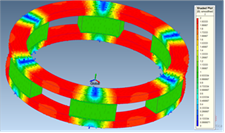
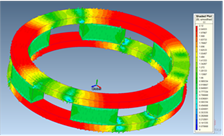
The magnetic circuit was optimised using a non-linear magnetostatic solver. A time-step non-linear transient solver was used to simulate the dynamic behaviour of the device. The output of the transient solver was coupled to an electrical circuit model to calculate the instantaneous current profile.
Prototype testing & modelling results
The FCL core was connected in series with the power supply and the load resistor. The current through the FCL was recorded for a range of supply voltage when the load resistor was briefly shorted. The test was repeated with the FCL replaced by the air-cored coil.
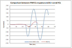
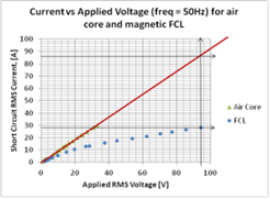
- For a ‘normal’ current of 3 Amps there is only small difference between the FCL and air-cored coil.
- For a current of 28 Amps, the impedance of the FCL is around 3 times that of the air-cored coil. In the FEM simulation at 30 Amps a change in current limitation was found to be approximately 4.5 times. This is reasonable given unavoidable differences between the models (such as assumption of isotropic permeability for grain oriented steel and reluctances introduced by small air gaps between the wound toroidal cores and the pole faces of the magnets).
- The performance of the core was found to be repeatable, showing no degradation of the permanent magnets following a “fault event”, as predicted by the FEM simulation.
Conclusions
Repeatable, current limiting capability has been demonstrated in a toroidal core, distributed magnet, orthogonally biased permanent magnet biased Fault Current Limiter.
European Regional Development Fund